Tutorial on How Mobile Phone Jammer Works
What is a Mobile Jammer?
A mobile jammer is an instrument used to protect the cell phones from the receiving signal. The mobile jammer device broadcasts the signal of the same frequency to the GSM modem. The jamming is said to be successful when the mobile phone signals are disabled in a location if the mobile jammer is enabled.
Cell phone jammer is an electronic device that blocks transmission of signals between a cell phone and a base station. By using the same frequency as a mobile handset, the cell phone jammer creates strong interference for communication between the caller and receiver. It is effective in blocking transmission of signals from networks including UMTS, 3G, CDMA, GSM and PHS.
Mobile phones operate at different frequency bands in different countries. For Canada, the 1900 MHz band is the primary band, particularly for urban areas. 850 MHz is used as a backup in rural areas. USA uses 850 and 1900 MHz bands, depending on the area. Europeans tend to use the GSM 900 and 1800 bands as standard. Middle East, Africa, Asia and Oceania also use these frequency bands. In Russia and some other countries, local carriers have licenses for 450 MHz frequency to provide CDMA coverage.
The use of different frequencies makes it difficult to have a jammer for all frequencies. However, the below mentioned formula can be used to calculate the required values.
For example, if mobile phones at your area work at 450 MHz, you need to generate 450 MHz with some noise to act as the blocking signal. Now the cell phone receiver will not be able to understand, which signal to receive. We have successfully blocked cell phone signals.
Here, 450MHz is the tuning frequency. Cell phone jammers for other frequency ranges are designed similarly. However, the signal range is very weak. Thus, this circuit works only for a range of 100 m.
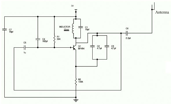
Cell Phone Jammer Circuit
The above circuit shows the mobile jammer circuit diagram and it is simple & easy to analyze. Basically the mobile jammer circuit consists of three main circuits. If the three main circuits are gathered then the output of that circuit is called as a jammer. The three circuits are mentioned below
- RF amplifier
- Tuning circuit
- Voltage controlled oscillator
As we can see that the transistor Q1, and the two capacitors C4 & C5 and also with one resistor can compose the RF amplifier. By using the tuned circuit the RF amplifier amplifies the signal and the amplification signal is given to the antenna with the help of the capacitor C6 this capacitor will remove the DC signal and permit the AC signal. If the transistor Q1 is in ON state, then the tuned circuit at the collector end will be tune ON and the tuned circuit consists of capacitor C1 & inductor L1 hence it act as an oscillator with zero resistance. This oscillator will produce the high frequency with minimum impair. Both the indicator & capacitor in the tuned circuit will oscillate the resonating frequency.
The operation of the tuned circuit is easy to learn & understandable. If the tuned circuit is ON then the voltage is stored by the capacitor according to the capacity and the electric energy is the main function of the capacitor. Once the capacitor is fully charged it will allow the charge to flow through an indicator. Basically the inductor is used to store the magnetic energy through this voltage across the capacitor it will get decreased automatically, at the same time total magnetic energy is stored in the inductor and the charge of the capacitor will be zero. The inductor of the magnitude will be decreased and the capacitor will be charged with the help of current in a reverse polarity manner. After some period of time capacitor is charged completely and the magnetic energy transversely the inductor will be zero. Once again the capacitor will produce the charge to the inductor and becomes zero. After some time interval the capacitor will be charged with the help of an inductor and the capacitor will become zero.
The internal resistance is generated hence the oscillation will be stopped. The supply of the RF amplifier is through the capacitor C5 to the collector terminal which is before C6 for gain signal to the tuned signal. For generating noise the capacitors C2 and C3 are used for the frequency generated by the tuned circuit and these capacitors will produce the electronic pulses in random.
The cell phone Jammer works with the frequency of 450MHz if this frequency is hunk we need to generate the 450MHz frequency with same noise which is acted as a blocking signal because the receiver of the cell phone signal will not be able to understand the received signal. By this circuit we can able to block the cell phone signals.
Description:
For any jammer circuit, it’s essential to have three important subcircuits.
RF amplifier
Voltage Controlled Oscillator
Tuning circuit
These 3 circuits, when combined together form an efficient cell phone jammer circuit.
Applications of Mobile Jammer
- The Mobile jammers are used in the classrooms, and library to maintain silence
- It is used in the seminar halls and meeting rooms to avoid disturbances
- It is used in the hospitals
- The mobile jammers are used in the temples, churches, etc.
Different Types of Mobile Jammers
There are different types of mobile jammers which are given below
- Remote Controlled Mobile jammer
- Adjustable Mobile Jammer
- School & Prison Mobile Jammer
- Explosion Proof Mobile jammer
- Police & Military Mobile Jammer
- Portable Mobile Jammer
Working
RF amplifier circuit comprises of the transistor Q1, capacitors C4, C5 and resistor R1. This RF circuit amplifies the signal generated by the tuned circuit. The amplified signal is given to the antenna through capacitor C6. It blocks DC and allows only the AC component of the signal to be transmitted.
When transistor Q1 is turned ON, the tuned circuit at the collector turns ON. The tuned circuit consists of capacitor C1 and inductor L1. This acts as an oscillator with zero resistance. It produces very high frequency with minimum damping.
When the circuit is ON, voltage is stored in the capacitor. Once the capacitor is completely charged, it allows charge to flow through the inductor. When current flows through the inductor, it stores magnetic energy corresponding to the voltage across the capacitor. At a certain point, the inductor reaches its maximum and the charge or voltage across the capacitor turns to zero.
Now the magnetic charge through the inductor decreases and the current charges the capacitor in opposite or reverse polarity. The process repeats and after a while, inductor charges the capacitor and becomes zero.
This process runs till internal resistance is generated and the oscillations stop. RF amplifier feed is given through capacitor C5 to the collector terminal before C6. The capacitors C2 and C3 generate pulses in a random fashion (noise) at the frequency generated by the tuned circuit.
The RF amplifier boosts the frequency generated by the tuned circuit. The frequency generated by the tuned circuit and the noise signal generated by the capacitors C2 and C3 is combined, amplified and transmitted.
Note
This circuit can block signals only within a 100 meter radius.
Usage of this type of circuits is banned and illegal in most countries.
This circuit is also used in TV transmission and remote controlled toys.
If the circuit is not working properly, try increasing resistor and capacitors values in the circuit.
Power supply for the circuit should not exceed 3 Volts.
Note: -
The cell phone jammer is an untested prototype circuit and banned in several countries. Keeping in with those regulations, we might not be able to help you out with the exact values.
Blog Presented by
~Rakesh yadav
( Electronis and Comnunication )
Email id : Rarakesh30122017@gmail.
"The Innovation Hub"
(Team Member)
#TIH2019
Email id .... theinnovationhub2019@gmail.com
"The innovation hub" join us on following sites.....
Linkedin link ..https://www.linkedin.com/in/the-innovation-hub-7a3286186/
Innovative mixing of songs- channel END BAND link...https://www.youtube.com/channel/UCbiOBBTYpVLjgTXjIaiel2A
"Trending Research" you tube channel link..https://www.youtube.com/channel/UCtSCDLJmLmu6eSEq44HfWIg


Comments
Post a Comment